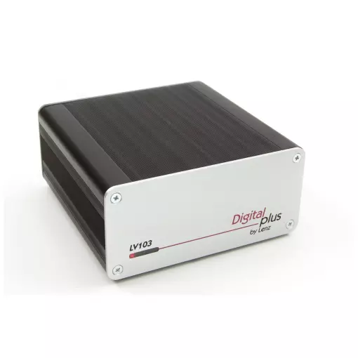
Digital amplifier plus LV103
If you need more power.
The successor to the LV102 is also designed to meet the safety requirements and operating conditions of the railway model. If required, the track voltage and output current can be individually adapted to the conditions and set, the maximum current supplied is 5 amps. The LV103
- is ready for RailCom operation .
- has an integrated RailCom global detector
Technical data:
| Power supply (input voltage) |
with alternative tension: min. 14 volts, max. 19 volts with pure DC voltage: min. 14 volts, max. 24 Volts It makes sense to select an input voltage about 2 V higher when the DC voltage supply is equal to or slightly lower than that obtained with the defined output voltage (voltage on channel). This prevents unnecessary heat loss in the device, which can lead to premature thermal shutdown. |
| output voltage (voltage on track) |
The voltage on the track is adjustable between 11 V and 22 V in increments of 0.5 V. This load may be lower, under load, depending on the transformer used. By default, an output voltage of 16 V is defined. |
| output current | Depending on the transformer used, its voltage and the channel voltage set, the DC current that the LZV200 amplifier can deliver is different. Example: with the TR150 transformer and setting the channel voltage to 16 V, the DC current is 4.3 A. | .
| Overload protection | |
| RailCom sensor | The LV103 is equipped with a global RailCom detector. This detector receives the data sent by the decoders in channel 2 of the RailCom packets. This data is transmitted via lines C, D, E to the LZV200 control centre. |
| case | aluminium |
How much power do you need?
The power required by a model railway system depends on the consumption of all moving locomotives, interlocked locomotive functions, wagon lighting as well as functional models such as cranes etc. If the performance of the LZV100 / LZV200 is not sufficient to supply all consumers safely, the track configuration is divided into several Power Des sections, each supplied by its own amplifier. The size of these service areas must be dimensioned so that no area requires more power than the connected amplifier can supply. Control signals are received by the additional amplifiers from terminals C and D of the LZV100 / LZV200. Each amplifier requires its own power supply transformer, which must withstand the respective maximum current in continuous operation.
Determining the amplifiers required
Form the sum of the current consumption of all simultaneously running locomotives and lit wagons. For example:
6 locomotives with a current consumption of 0.7 A each plus 40 bulbs with a consumption of 0.05 A each in illuminated carriages generate a total current consumption of 6.2 A. Divide this total current consumption by the maximum current an amplifier can supply. and you get the number of service areas.
LV103 amplifier: Part number: 22103, dimensions: 120 x 55 x 120 mm
NOTICE of use here: https://www.lenz-elektronik.de/pdf/b_22103_def.pdf


